
Audio Dsp Demystified Sampling
Through this post and the following ones, I will do my best to provide you with the basic knowledge you need to understand and implement digital audio signal processing. The idea came from a conversation with my friend Chad Fowler who’s a well-known software developer, leader but also a well accomplished musician. Chad was interested in learning the basics of DSP and I can only assume he doesn’t have time to 42 books on the topic, white papers, PHD thesis and try to decipher complex math equations. Most DSP code out there is written in C, Assembly or C++ due to the fact that latency is really problematic for real-time audio processing applications (FPGAs & chipsets with DSP specific instructions are also used). There are also a lot of great/old libraries already available for those languages. But my goal here isn’t to teach how to use existing libraries, but to teach how they work so you can implement your own or make educated choices. I should note that I’m not an expert in the matter, I have never implemented complex real-time DSP and this series is only meant as an introduction to the topic.
TL;DR intro series teaching programmers the basic audio DSP concepts in a practical manner. No DSP knowledge is expected.
Analog to Digital conversion
To be able to access and manipulate audio data via our code, an audio signal needs to be converted from analog to digital. This is not something you usually implement yourself, in most cases it is done at the sound card level. Sound cards do the job of converting the signal, in other words, they are analog to digital converters (ADC).

It’s very important to understand how the conversion is done because it has direct repercussions on what we will do.
We have a continuous signal (the audio signal) and we need to convert it into numerical values. The numerical values needs to represent the sampled analog signal as closely as possible. To do that, a discrete signal needs to be created. A discrete signal is a fancy name for a time series representing the sampled signal. In other words, we measure the signal at a certain frequency (let’s say 44,100 times a second) and each value (an integer or a floating-point we call a sample) is added to our series. (This article assumes we are using PCM representation).

Sampling rate
The amount of time per second we take a sample from our analog signal is called the sampling rate. Common audio sampling rates are 44.1kHz, 48kHz and sometimes 96kHz.
There is a very important explanation about why we need to sample at a value greater than 40kHz.
The human hearing range falls into a frequency range of 20Hz to 20,000 H (that said you probably don’t hear very much above 17kHz). A requirement for our analog to digital conversion is that we can capture and then later on recreate an analog signal that will cover the entire frequency range we are interested in.
The reason we need to sample at a rate greater than 40kHz is due to the findings of Harry Nyquist.
Nyquist, studied and wrote about conversion of continuous to discrete signals.
One of the discoveries he made is called the Nyquist rate and simply put it says
that you need to sample at at a greater frequency than twice the bandwidth you want. Since we are trying to sample a range of 20,000Hz
we need to sample at 2x20000 = 40000 to cover the entire frequency range.
Fun fact, the default 44.1kHZ sampling rate comes Sony setting the standard by recording audio content on video equipment and wanting to have a system that was PAL/NTSC compatible (PAL runs at 25fps, NTSC at 30fps). They were able to store the exact same amount of 44,100 samples per seconds using different amounts of lines/frames.
Bit rate
The precision of the numerical value we use to store the sample is called the bit depth. The bit depth will change the range of values we capture, take for instance the sampling example below.

The analog signal in red is being sampled at a 4-bit bit depth meaning that each sample is represented by an integer taking 4 bits in memory.
4 bits give us a maximum range of 16 integer values (4*4) Our sample value will be between 0 and 15. 4-bit precision really isn’t enough
to properly represent the reach dynamic range of audio signals.
Most audio content is sampled at 16 or 24 bit (8, 20 and 32 bit depths are also sometime used). A 16-bit integer resolution
offers a dynamic range of 96 dB (which can be improved using dithering but that’s outside of the scope of this article).
Too low of a resolution and you are missing auditive information (and getting extra noise), too high of a resolution and it’s a waste. 32 floating-point bit depth is often used later on in the audio chain when doing complex audio processing. This process allows for greater precision when manipulating audio data and rounding can have a negative effect on the output (DAWs, synthesizers, effects…). The data is usually converted back to the source bit depth making things easier/transparent to the caller.
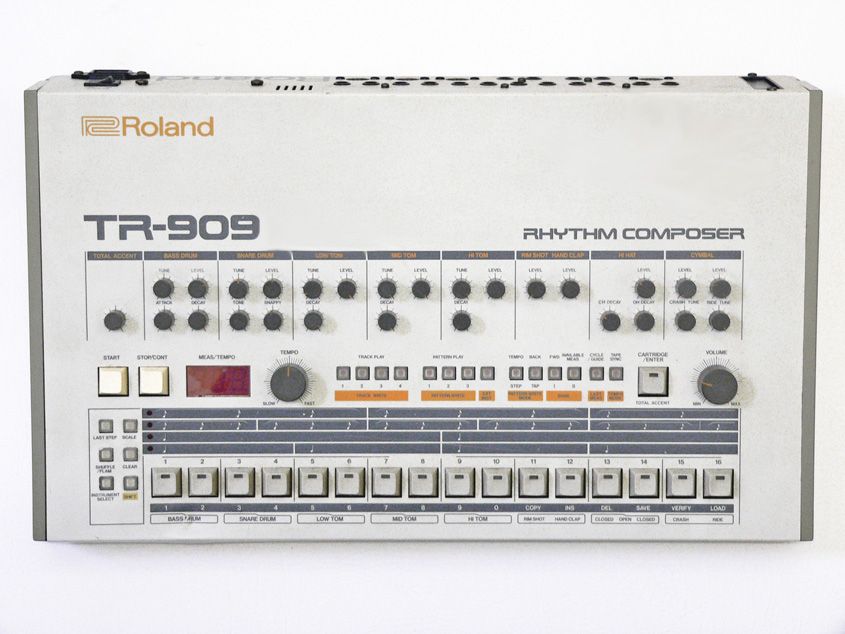
Fun fact: The famous TR-909 drum machine only used a bit depth of 6-bit!
File formats: WAV & AIFF
Now that we learned how the audio signal is being converted to a digital stream, it’s interesting to see how it’s being stored. The 2 main uncompressed PCM formats are WAV and AIFF. These formats store the same data slightly differently and provides valuable information of the stream content via file headers and data chunks. To be able to do any kind of offline processing, we need to be able to read and write such formats. In a future post, we will write a coder/decoder that explains how these file formats work (and get a sneak peek into lossy compression formats such as MP3).